CNG pressure regulating station
Get In Touch →
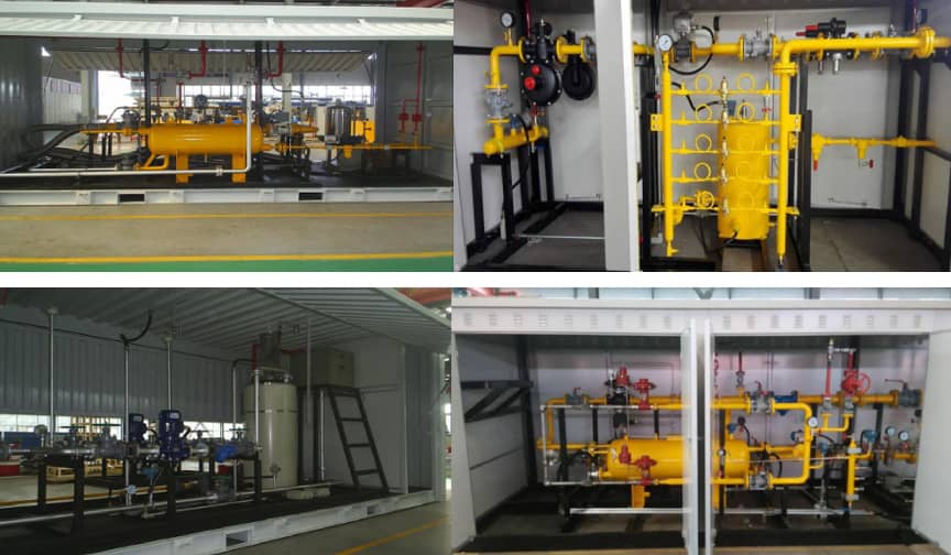
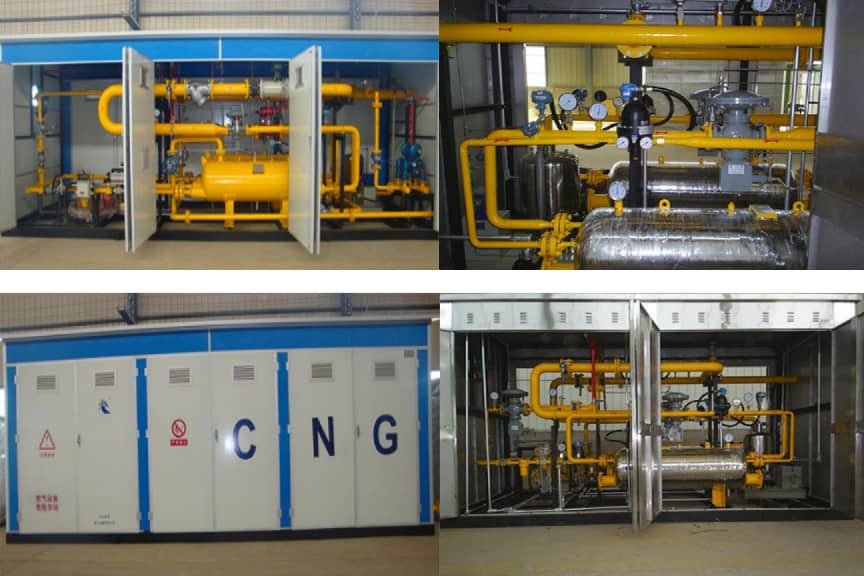
Overview
With the transformation of China’s energy structure and continuously strengthened environmental protection efforts, the development and utilization of natural gas have achieved rapid growth. Compressed Natural Gas (CNG) refers to wellhead natural gas or pipeline natural gas that is purified and compressed for high-pressure storage and transportation. Upon arrival at the destination, it undergoes multi-stage heat exchange and pressure reduction before being fed directly into the pipeline network to supply various users.
Economically viable distance for a CNG pressure regulating station from the gas source is within 300 km, generally not exceeding 500 km. The recommended supply scale covers 2,000–4,000 households with a gas supply volume of 200–5,000 Nm³/h. Either excessively large or small supply capacity will raise the unit gas cost.
Compared with long-distance transmission pipelines, this system features lower investment, shorter construction cycles and faster capital recovery. It can serve as a peak-shaving and standby gas source for long-distance pipelines in the future.
Process Introduction of CNG Pressure Regulating Station
Working Principle of CNG Pressure Regulating Station
High-pressure natural gas inside skid-mounted tank trucks is preheated, depressurized stage by stage, and processed through safety control, metering and odorization to bring the gas pressure up to the standard-compliant level for pipeline delivery. Based on pressure regulation mechanisms, it can be classified into two-stage pressure regulation and three-stage pressure regulation.
Structure Introduction of CNG Pressure Regulating Station
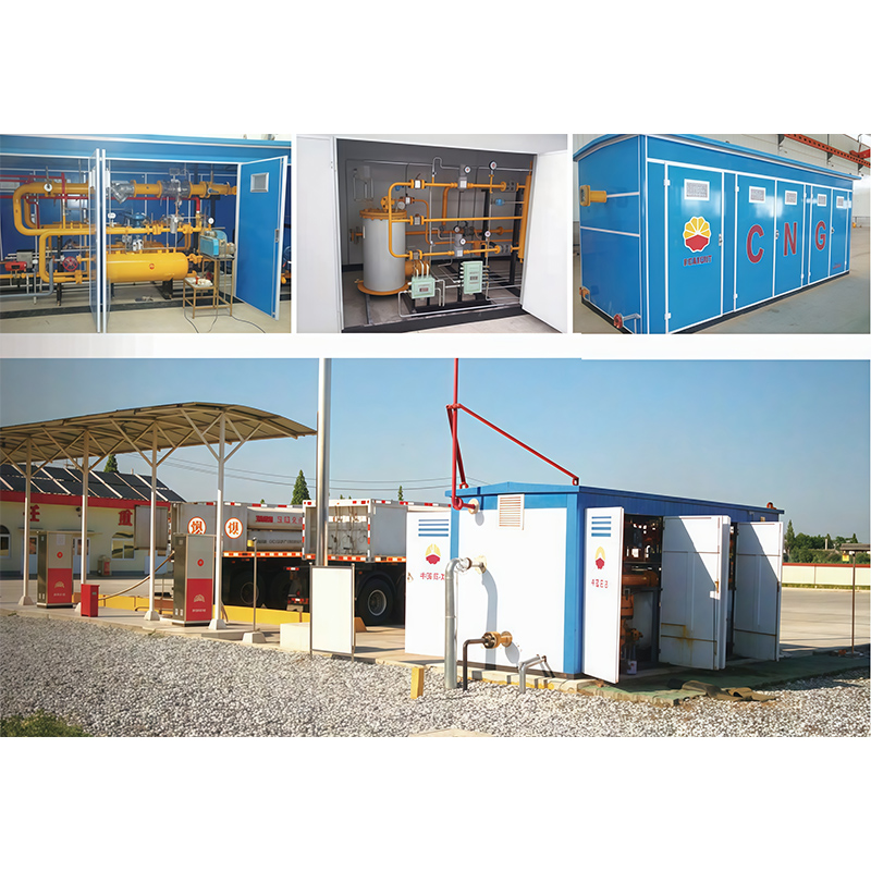
According to on-site layout and equipment functions, a CNG pressure regulating station consists of:
- Unloading System (high-pressure hoses, quick connectors, high-pressure valves)
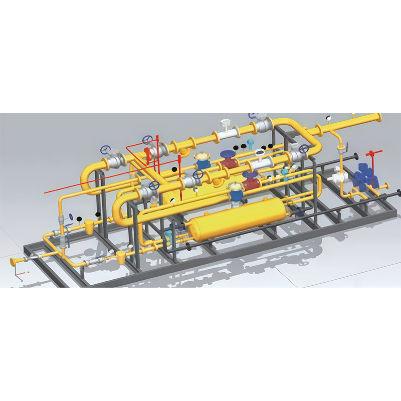
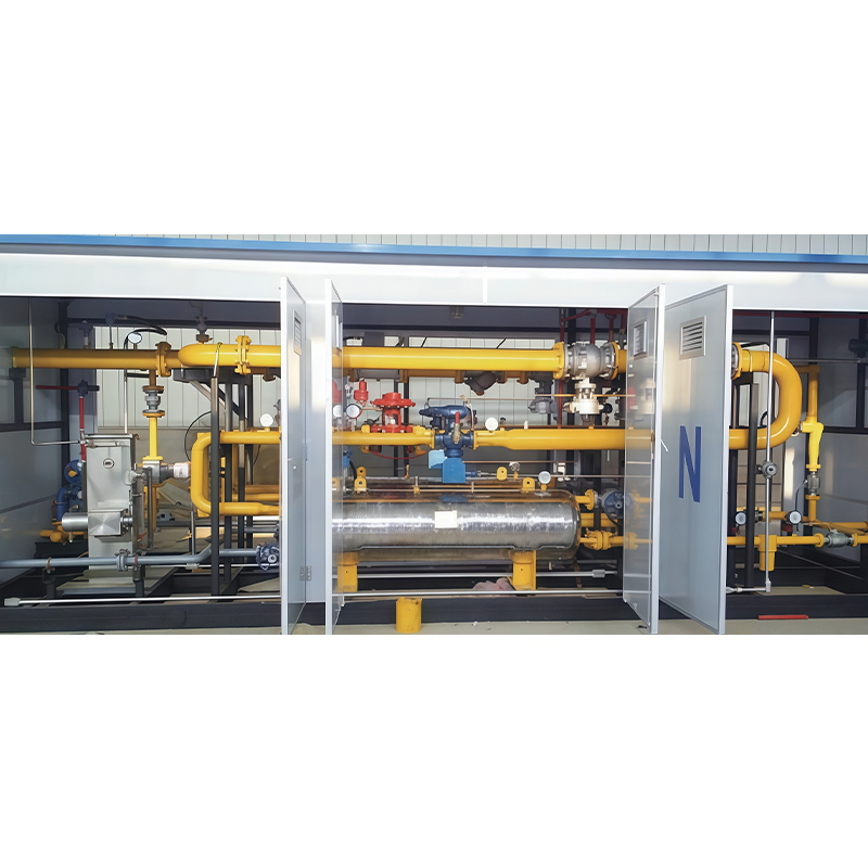
- Pressure Regulating & Heat Exchange System (high-pressure emergency shut-off valves, heat exchangers, pressure regulators, vent valves)
- Flow Metering System (flow meters)
- Control System (central control console)
- Heating System (gas-fired boilers, hot water pumps, etc.)
High-pressure natural gas from the skid-mounted tanker first passes through the unloading system into the pressure regulating and heat exchange system. Inside this system, the gas undergoes two cycles of heat exchange plus two or three stages of pressure regulation before entering the flow metering and odorization system, and finally feeds into the pipeline network. The heating system supplies heat required during gas depressurization, while the control system monitors the whole facility.
Pressure Regulation Process
A. Two-stage Pressure Regulation Process
First, connect to the skid-mounted steel tanker via high-pressure hoses and quick connectors. Compressed natural gas flows through ball valves and high-pressure shut-off valves into the primary heat exchanger to be heated. The gas is then depressurized by the primary regulator to 1.0–4.0 MPa, sent to the secondary heat exchanger for reheating and regulated by the secondary regulator down to 0.1–0.4 MPa. Afterwards, the gas passes through a flow meter for metering, followed by gas odorization, and is delivered into the medium-pressure pipeline network. Interlock control of gas pressure, temperature, flow rate, water temperature at all stages, key valve operation and switching between the two lines inside the regulating station is implemented by the central control console.
B. Three-stage Pressure Regulation Process
First, connect to the skid-mounted steel tanker via high-pressure hoses and quick connectors. Compressed natural gas flows through ball valves and high-pressure shut-off valves into the primary heat exchanger to be heated. The gas is depressurized by the primary regulator to 3.0–7.5 MPa, then heated in the secondary heat exchanger and regulated by the secondary regulator to 1.6–2.5 MPa. After tertiary pressure regulation to 0.1–0.4 MPa, the gas enters the flow meter for metering. Finally, the fuel gas undergoes odorization and is fed into the medium-pressure pipeline network. Interlock control of gas pressure, temperature, flow rate, water temperature at all stages, key valve operation and switching between the two lines inside the regulating station is implemented by the central control console.
CNG Pressure Regulating Station Performance Parameter Table
| Specifications | YG-300 | YG-500 | YG-1000 | YG-1500 | YG-2000 | YG-3000 | YG-4000 |
|---|---|---|---|---|---|---|---|
| Max Hourly Flow (Nm³/h) | 300 | 500 | 1000 | 1500 | 2000 | 3000 | 4000 |
| Structure Type | \multicolumn{7}{c}{One standby, one in service} | ||||||
| Heat Exchange Stages | \multicolumn{7}{c}{Two-stage heat exchange} | ||||||
| Pressure Regulation Stages | \multicolumn{4}{c}{Two-stage pressure regulation} | \multicolumn{3}{c}{Three-stage pressure regulation} | |||||
| Inlet Water Temperature (℃) | 65–85 | 65–85 | 65–85 | 65–85 | 65–85 | 65–85 | 65–85 |
| Primary Heat Exchange Return Water Temp. (℃) | 60 | 60 | 60 | 60 | 60 | 60 | 60 |
| Secondary Heat Exchange Return Water Temp. (℃) | 60 | 60 | 60 | 60 | 60 | 60 | 60 |
| Outlet Gas Temperature (℃) | 10–20 | 10–20 | 10–20 | 10–20 | 10–20 | 10–20 | 10–20 |
| Gas Pressure after Primary Regulation (MPa) | 1.0–4.0 | 1.0–4.0 | 1.0–4.0 | 1.0–4.0 | 3.0–7.5 | 3.0–7.5 | 3.0–7.5 |
| Gas Pressure after Secondary Regulation (MPa) | 0.1–0.4 | 0.1–0.4 | 0.1–0.4 | 0.1–0.4 | 1.6–2.5 | 1.6–2.5 | 1.6–2.5 |
| Gas Pressure after Tertiary Regulation (MPa) | – | – | – | – | 0.1–0.4 | 0.1–0.4 | 0.1–0.4 |
| Outlet Gas Pressure | 0.1–0.4 | 0.1–0.4 | 0.1–0.4 | 0.1–0.4 | 0.1–0.4 | 0.1–0.4 | 0.1–0.4 |
| Primary Venting Pressure (MPa) | 1.3–5.2 | 1.3–5.2 | 1.3–5.2 | 1.3–5.2 | 3.9–9.75 | 3.9–9.75 | 3.9–9.75 |
| Secondary Venting Pressure (MPa) | 0.13–0.52 | 0.13–0.52 | 0.13–0.52 | 0.13–0.52 | 2.08–3.25 | 2.08–3.25 | 2.08–3.25 |
| Tertiary Venting Pressure (MPa) | – | – | – | – | 0.13–0.52 | 0.13–0.52 | 0.13–0.52 |
| Inlet Diameter | DN25 | DN25 | DN25 | DN40 | DN40 | DN50 | DN50 |
| Outlet Diameter | DN50 | DN80 | DN80 | DN100 | DN100 | DN150 | DN150 |
| Matched Boiler Power (kcal) | 20,000 | 25,000 | 50,000 | 100,000 | 100,000 | 150,000 | 200,000 |