Filter Separator
Get In Touch →Filter Separator
Overview
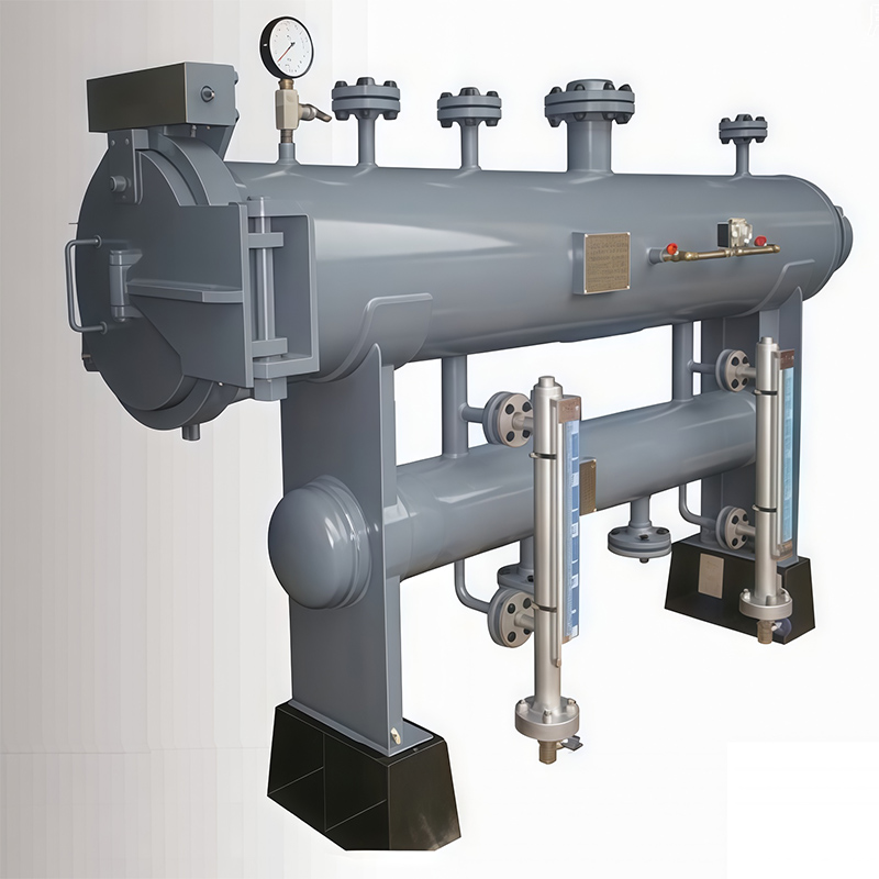
As an efficient gas-solid-liquid filtration and separation device, the filter separator is applicable to natural gas, coalbed methane and other media. It removes solid particles such as dust and rust as well as liquid droplets from gas, reducing damage caused by impurity-laden gas to compressors, flow meters, burners, instruments and other equipment during transmission. High-performance filter separators play a vital role in protecting precision instruments and equipment within gas processing and transmission systems.
Working Principle
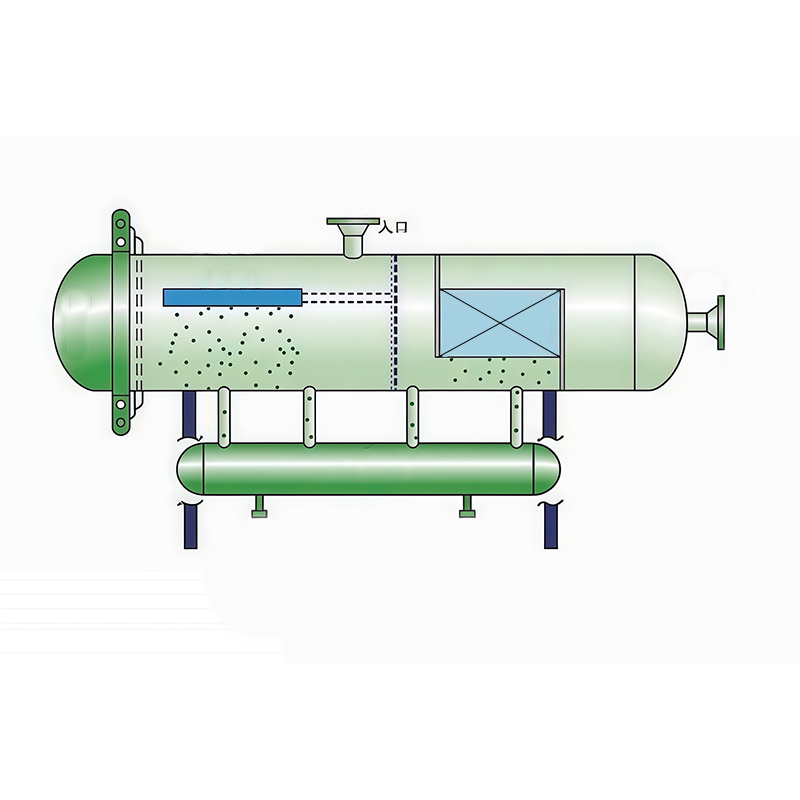
Gas carrying solid particles and liquid droplets enters the filter separator and first passes through filter elements for primary filtration. Solid particles are trapped while liquid droplets are coalesced. Owing to the structural features of filter elements, solid particles are retained on the outer surface of or accommodated inside the filter elements. Liquid particles coalesce into larger droplets and flow into the liquid storage tank.
Gas after primary filtration flows into the separation chamber. Mist-like liquid entrained in the gas is captured by a mist eliminator, continuously coalescing on its inner surface to form larger droplets, which separate from the gas under gravity.
Technical Parameters
Design Standard: GB/T150-2024 Pressure Vessel
Structure Type: Vertical, Horizontal
End Cover Type: Quick-opening Door, Flange Cover
Connecting Flange Standard: HG/T20592 ~ HG/T20615-2009 or ANSI B16.5, etc.
Filter Element Material: Polyester Fiber
Performance Indicators
Design Pressure: ≤10 MPa
Design Temperature: -40℃ ~ 80℃
Initial Pressure Drop: ≤5 kPa
Filtration & Separation Accuracy and Efficiency:
Solid: ≤1 μm, 99%
Liquid: ≤5 μm, 98%
Filtration & Separation Accuracy Grades: 0.3 μm, 1 μm, 3 μm, 5 μm, 10 μm, 20 μm, 50 μm
Application Scope
For filtration and separation of natural gas, coalbed methane and biogas;
Removal of desiccant particles and liquid droplets downstream of drying beds;
Removal of catalyst powder and liquid droplets downstream of catalyst beds;
Gas filtration and separation before metering and pressure regulating stations;
Gas filtration and separation for urban gas distribution systems.
Structure Type
Type K, Type F
Type K — Quick-opening Type
Type F — Flange Cover Type
Installation Type
Type V, Type H
Type V — Vertical Installation
Type H — Horizontal Installation
Specification Definition
Example: DN250/DN100 – Main shell diameter DN250, inlet and outlet diameter DN100
Installation and Connection Method
Filter separators can be installed horizontally or vertically. For horizontal installation, the horizontal tolerance of the main axis of the equipment shall be less than 5/1000. For vertical installation, the verticality tolerance of the main axis of the equipment shall be less than 3/1000. The equipment adopts flange connection and is equipped with vent valve, safety valve, pointer differential pressure gauge, liquid level gauge and pressure gauge.
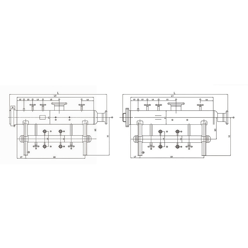
Structural Dimension Table for FH Type and KH Type Filter (Unit: mm)
| Filter Specification | Structural Dimensions | Nozzle Nominal Size DN | |||||||||||||||||
|---|---|---|---|---|---|---|---|---|---|---|---|---|---|---|---|---|---|---|---|
| L | L1 | L2 | L3 | L4 | L5 | L6 | L7 | L8 | H | D1 | D2 | 1 | 2.5 | 3 | 4.6 | 7.8 | 9–12 | 13.14 | |
| DN250/DN100 | 2400 | 1650 | 150 | 200 | 200 | 300 | 250 | 200 | 300 | 700 | 250 | 100 | 15 | 32 | 40 | 100 | 32 | 100 | 15 |
| DN300/DN150 | 2400 | 1700 | 150 | 200 | 200 | 300 | 250 | 200 | 300 | 700 | 300 | 150 | 15 | 40 | 40 | 150 | 40 | 150 | 15 |
| DN350/DN200 | 2900 | 1800 | 200 | 200 | 200 | 300 | 250 | 200 | 400 | 700 | 350 | 150 | 15 | 40 | 50 | 200 | 40 | 200 | 15 |
| DN400/DN250 | 2900 | 2000 | 200 | 200 | 200 | 350 | 250 | 200 | 400 | 800 | 400 | 200 | 15 | 40 | 50 | 250 | 40 | 250 | 15 |
| DN450/DN250 | 2900 | 2100 | 200 | 200 | 200 | 350 | 250 | 200 | 500 | 800 | 450 | 200 | 15 | 40 | 50 | 250 | 40 | 250 | 15 |
| DN500/DN300 | 3600 | 2100 | 200 | 200 | 200 | 350 | 250 | 200 | 600 | 800 | 500 | 250 | 15 | 40 | 50 | 300 | 40 | 300 | 15 |
| DN600/DN350 | 3800 | 2200 | 200 | 250 | 250 | 350 | 300 | 250 | 600 | 800 | 600 | 250 | 15 | 40 | 50 | 350 | 40 | 350 | 15 |
| DN700/DN350 | 2400 | 2200 | 200 | 250 | 250 | 400 | 300 | 250 | 700 | 900 | 700 | 250 | 15 | 50 | 80 | 350 | 50 | 350 | 15 |
| DN800/DN400 | 2400 | 2400 | 250 | 250 | 250 | 400 | 300 | 250 | 700 | 900 | 800 | 300 | 15 | 50 | 80 | 400 | 50 | 400 | 15 |
| DN900/DN400 | 2400 | 2400 | 250 | 300 | 300 | 400 | 350 | 250 | 800 | 900 | 900 | 300 | 15 | 50 | 80 | 400 | 50 | 400 | 15 |
| DN1000/DN400 | 2900 | 2450 | 250 | 300 | 300 | 400 | 350 | 300 | 800 | 1000 | 1000 | 350 | 15 | 50 | 100 | 400 | 50 | 400 | 15 |
| DN1200/DN400 | 2900 | 2450 | 250 | 300 | 300 | 400 | 350 | 300 | 800 | 1000 | 1200 | 400 | 15 | 50 | 100 | 400 | 50 | 400 | 15 |